Cane enclosure: four-eye and two-eye versions
Two designs on the same 64 mm wide, 30 mm deep box. A carries two HC-SR04 boards: upper pair straight ahead, lower pair in a nose angled 18° down. B carries one HC-SR04 facing forward and is 20 mm shorter. Both have a centre indicator LED, a power slide switch, a micro-USB charge opening and two bottom cable outlets. Both hold Tope's controller board, battery and wiring on a removable tray, and clamp to the cane with two screw collars. Nothing has been sliced or printed.
3D bench
Hardware shown is the nominal size. Wires are drawn to show routing; real wires will be loose.
Still renders
Rendered from the CAD. Box shown see-through so the sensors, controller, battery and wiring are visible.
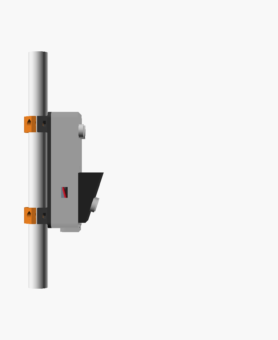
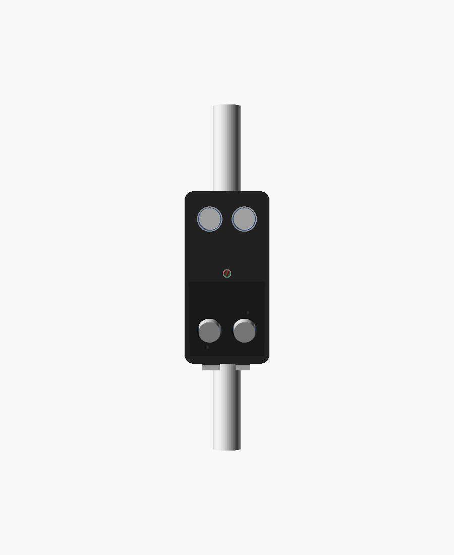
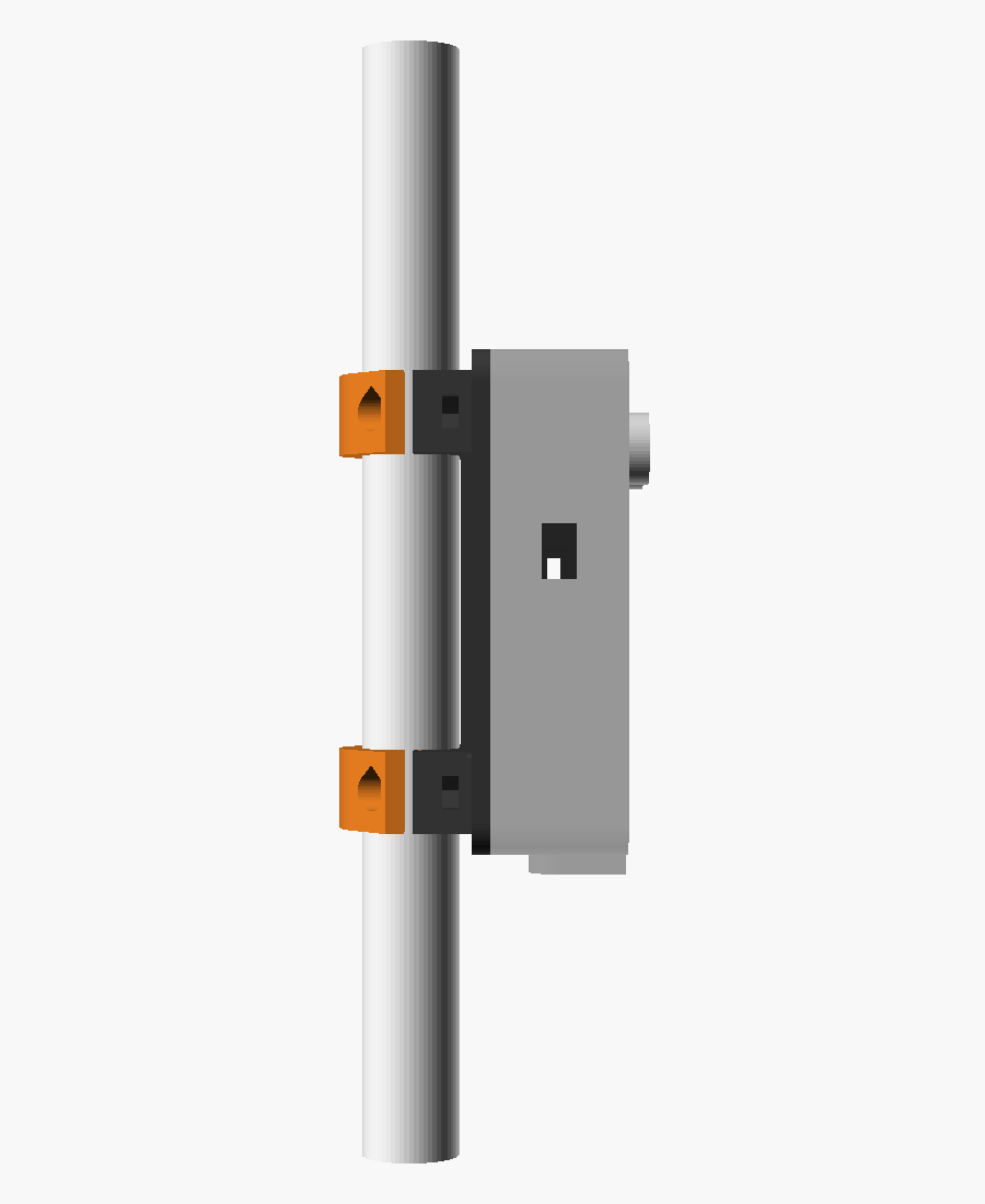
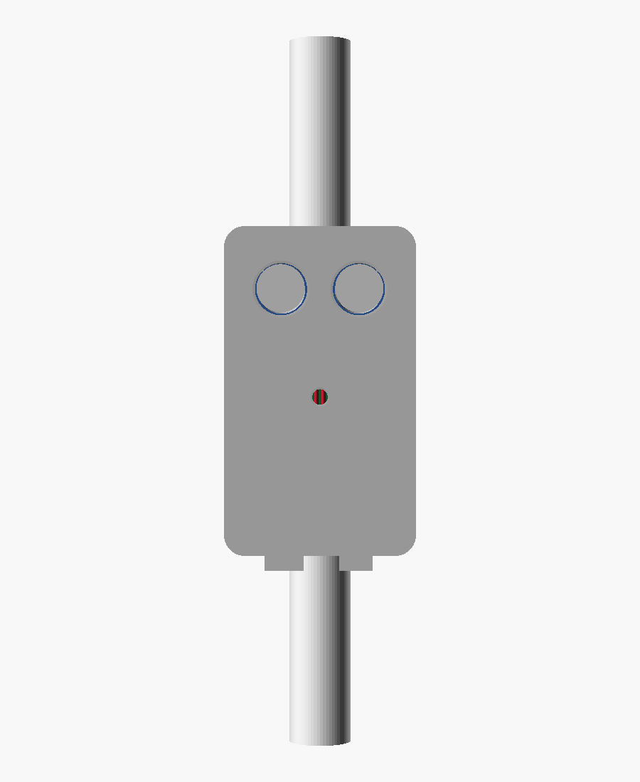
Dimensioned views
Key dimensions
| Item | A · 4 eyes | B · 2 eyes | Basis |
|---|---|---|---|
| Box outside (W × H × D) | 64 × 130 × 30 | 64 × 110 × 30 | 146 approved envelope; B shortened |
| Inside cavity | 59.2 × 125.2 × 27.6 | 59.2 × 105.2 × 27.6 | 2.4 mm walls (6 lines) |
| Sensor openings | 4 × Ø17.4 | 2 × Ø17.4 | 16 mm can + 0.7 mm per side confirm on gauge |
| Eye centre pitch (side by side) | 26.0 | 26.0 | HC-SR04 nominal measure |
| Upper eye height (from box top) | 21.0 | 21.0 | clears corner screw bosses |
| Lower eyes | axis 18° down, centre 26 mm above box bottom | none | Founder 18° |
| Upper to lower eye spacing | 83 mm (vertical) | n/a | keeps the two beams apart |
| Nose (lower sensor housing) | 56 wide · sticks out 8 to 26.2 | none | 4 × M3 from inside the box |
| Can protrusion past the face | 5.1 | 5.1 | board 4.5 mm behind the wall |
| Sensor board seat | 4 rest ribs + 2 screw tabs per board, M3 × 8 self-tapping | no screws through the HC-SR04 | |
| Controller cradle | 31 × 56 inside, 3 mm pads, 4 tie-slot pairs, 10 mm parts height | Tope's vero ~30 × 55 measure | |
| Battery space | 51 × 35 cradle on tray, strap channel | 51 × 35 pocket on front wall | 503450 LiPo placeholder identify |
| Clearance: sensor plugs to controller parts | 3.4 | 3.4 | CAD clash check: no overlap |
| Cane clamp | 2 split collars 18 wide, bore Ø22, 2 × M4 + captured nut each; cane axis 18 mm behind box | bore is a placeholder measure cane | |
| Total depth, front to cane back | 90 (nose top) | 69 (can tips) | includes clamp caps |
| Indicator LED | Ø5.2, centre, 68 up | Ø5.2, centre, 53 up | 5 mm LED on an inner sleeve, dome ~1 mm proud |
| Power switch | right wall, 66 up | right wall, 62 up | slide-switch slot 6.5 × 3.2 + body pocket 9 × 4 confirm switch |
| Charge port | left wall, 40 up | left wall, 66 up | micro-USB (Android) plug opening 12 × 7.5 |
| Cable outlets | Ø8 + Ø6 in the bottom, with strain-relief collars | vibration motor / handle | |
What changed from the last design (146)
| Item | 146 (printed on the Anet) | Now | Why |
|---|---|---|---|
| Openings | 2 × Ø17.0, one each | A: 4 × Ø17.4 · B: 2 × Ø17.4 | Two full HC-SR04 boards, two eyes each (Founder) |
| Eye arrangement | one column (COL) | side by side, 26 apart | HC-SR04 pins then point down, so the plugs fit inside without bending |
| Box | 64 × 130 × 30 | A same · B 64 × 110 × 30 | B is the shorter two-eye test |
| Nose | 18°, 50 wide | 18°, 56 wide (A only) | a 45.6 mm board now fits across it |
| Electronics | two loose trays 50 × 65 and 50 × 38 | one tray: battery + controller cradles, tie slots, pads | one part to fit Tope's boards to, screws to the back plate |
| Ports | 7 mm round switch hole, USB-C slots | centre LED, slide switch slot, micro-USB charge, 2 cable outlets | Founder 3 Nov |
| Clamp spine | touched the cane by 1 mm | 0.5 mm gap | clash found in the CAD check |
| Printer | Anet A8 Plus, SD card | Bambu X1 Carbon, one plate | new printer |
Printing plan (after you approve)
Step 1 · Fit gauge (recommended first)
The front wall and ribs around the upper eyes, plus the nose for A, with the screw tabs. You press the real HC-SR04 boards in and check the eyes line up before printing the whole box.
- A gauge: 64 × 32 slice + nose + 4 tabs
- B gauge: 64 × 32 slice + 2 tabs
- Small print; time comes from the slicer
Step 2 · Full set, one plate
All parts on one 256 × 256 X1 Carbon plate with no overlaps: box, back plate with collars, 2 caps, tray, tabs, and the nose for A.
- A: 10 pieces, tallest 30 mm
- B: 9 pieces, tallest 30 mm
- Grams and time: reported after slicing in Bambu Studio
Hardware to have ready
- M3 × 10: 4 (box to back plate)
- M3 × 8 self-tapping: 4 for A, 2 for B (sensor tabs)
- M3 × 8: 4 (nose, A only)
- M3 × 6 countersunk: 4 (tray)
- M4 × 20 + M4 nut: 4 each (collars)
- 20 mm hook-and-loop strap, small cable ties, foam tape
Before the full print
Measure with calipers
- HC-SR04: can diameter, eye centre pitch, board size
- Cane: outside diameter where the box mounts
- Tope's controller board: tallest part and solder underneath (recovered: ESP32-C3 ~25 × 18, MPU6050 ~21 × 15, vero 55 × 30)
- Battery: type and size, and where the charge socket is
- Power slide switch: body size
Each number is one parameter in the CAD. A change regenerates both designs.
X1 Carbon connection
Bambu Studio is not installed on this Windows PC. I found no install, no app data and no Start menu entry, so I have not connected to the printer. Nothing has been sent to it.
Once Bambu Studio is installed and signed in to your Bambu account, I can confirm the printer is online and slice with the real X1C profile.
Source files
D:/ZAP-ENGINEERING/opus-enclosure-151-20261103/enclosure_151.scad
One file; V="four" or V="two". Original COL, A2 and 146 files are kept read-only in originals-READONLY with SHA-256 sums.